DIGITAL MASTER - SLAVE CLOCK SYSTEM
The Schematic layout of the system is as give above .The Digital Clock system has one MASTER CLOCK & Multiple SLAVE CLOCKS. The data generated at the MASTER is transmitted to the SLAVES, using the RS-485 SERIAL mode of communication.
MASTER CLOCK :
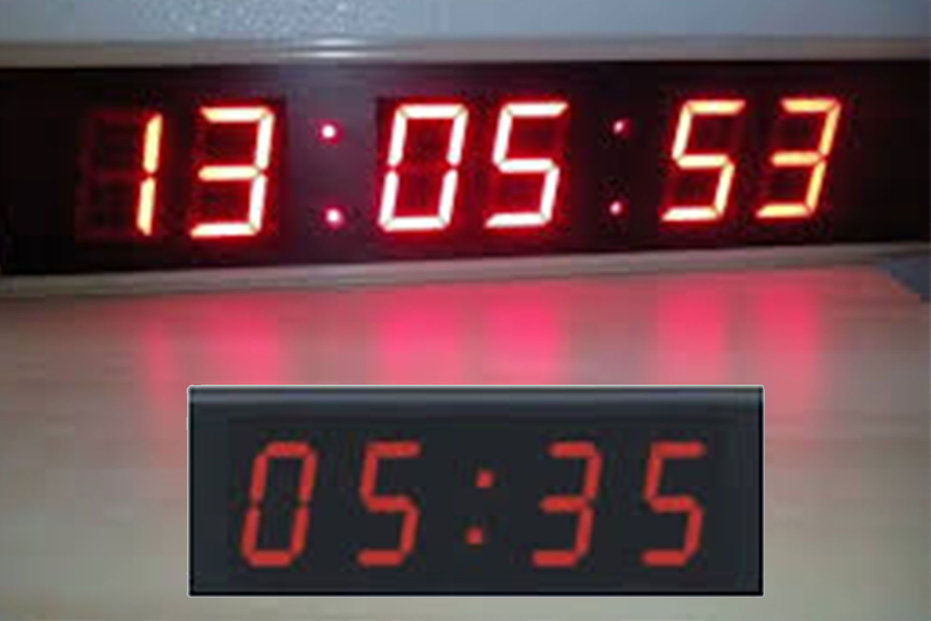
The master clock uses Micro-controller based circuitry. Its Clock functions are generated from a quartz controlled RTC chip. The uniqueness of this chip is that it is backup on power failure by a LITHIUM battery and the low power consumption of the circuit gives a long battery life. The time is displayed using four digits of RED LED displays, two digits to the left . for HRS. and the two digits to the right for MINS. Two rugged Push-to-ON switches are used to set the clock .
SLAVE CLOCKS :
The data from the master clock is received through a 3 – core Cable using the Serial mode of communication & it is processed and displayed using Microprocessor-based circuitry. The time is displayed using RED LED displays. The Slave Clock in addition to being synchronized with the MASTER has its own RTC chip with Battery backup ,which continues to work independently providing normal Clock functions during a link failure with the master. All these inbuilt safety factors makes it a very reliable CLOCK system.
CABLE CONNECTION :
The three wires connected to the 3-terminal block at the Master has to be replicated at the Slaves.
Once the above has been set, the clock will display the correct time. In case of power failure, the LITHIUM battery will ensure that the clock keeps correct time, but the display will go off.
As per client requirement we can supply Master Clock with Computer / GPS connectivity.
DIGITAL MASTER - SLAVE CLOCK SYSTEM
The Schematic layout of the system is as give above .The Digital Clock system has one MASTER CLOCK & Multiple SLAVE CLOCKS. The data generated at the MASTER is transmitted to the SLAVES, using the RS-485 SERIAL mode of communication.
